- PRODUCTS
- MODEL LIST
- APPLICATIONS
- SUPPORT
- SALES/SERVICE
- BLOG
- ABOUT
Login
Shipping SBE 9plus, 25, and 25plus Temperature and Conductivity Sensors
Introduction
Improper disassembly of the ducted temperature and conductivity sensors (in SBE 25 and SBE 9plus systems) while removing them for calibration can result in a broken conductivity cell. These instructions guide you through the process of removing the sensors from the system for shipment to Sea-Bird for calibration.
The conductivity cell and the temperature probe are very fragile. Both the installation and removal procedures require slow, deliberate movements to avoid breaking the temperature or conductivity sensor. Therefore, Sea-Bird recommends that you perform these procedures in a lab, not on deck.
Description
The conductivity and temperature sensors (the conductivity sensor has a glass cell and the temperature sensor has a probe) are attached by a bracket and by plastic tubing called a TC Duct. The plastic (Delrin) TC Duct comes in two pieces: a T-Duct that fits inside the temperature sensor guard over the sensor probe, and a C-Duct that fits into the conductivity cell end. The two duct pieces are joined with flexible plastic (Tygon) tubing to form the TC Duct assembly.
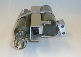 T and C sensors in SBE 9plus bracket |
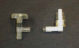 T-Duct and C-Duct; see left side of drawing 67027 for part numbers |
Removing Sensors from System
Note: sensor bracket shown below is from SBE 9plus.
- Remove the conductivity and temperature sensors and mounting bracket assembly from the CTD:
- Unscrew the locking sleeves from the temperature and conductivity sensor cable connectors by hand. If you must use a wrench or pliers, be careful not to loosen the bulkhead connector instead of the locking sleeve.
- Remove the cable connector from each sensor by pulling the connector firmly away from the sensor.
- Remove the quick-release plug from the conductivity cell.
- Remove the two 9/16 inch hex head aluminum bolts that secure the mounting bracket to the CTD’s end cap. Remove the mounting bracket from the CTD.
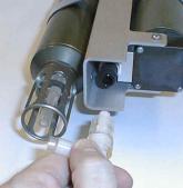
- Disconnect the T Duct from the C Duct:
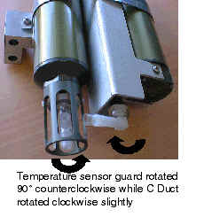
- Slowly rotate the temperature sensor guard by turning it counter-clockwise approximately 90 degrees. At the same time, rotate the C Duct clockwise slightly. The Tygon tube that joins the ducts flexes and slips off the T Duct as the T Duct twists out of its position.
Note: Do not force the C Duct, as this could break the conductivity cell. If rotating the C Duct is difficult, pour water over the duct area to dissolve buildup around the duct.
|
|
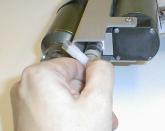
- Remove the C Duct from the conductivity cell:
- Carefully rotate the C Duct clockwise more. Do not force the C Duct, as this could break the conductivity cell. If rotating the C Duct is difficult, pour water over the duct area to dissolve buildup around the duct.
- Once loosened, gently pull the C Duct straight out from the conductivity cell.
- Store the C Duct for reinstallation when the sensors have returned from calibration.
|
|
|
- Retighten the temperature sensor guard by hand.
- Loosen the mounting bracket strap screw, and slide the sensor(s) from the bracket. If both sensors are being shipped, SBE 9plus sensors can be shipped in their mounting bracket.
- The conductivity cell is stored and shipped dry, to prevent damage caused by freezing:
- Rinse the conductivity cell with clean, de-ionized water.
- Drain and gently blow-dry the conductivity cell.
- Ship the sensor(s) in a package with cushioning material to protect them from damage during shipment.
Reinstalling TC Duct and Sensors
When re-installing the TC Duct, follow the instructions in reverse. Position the temperature sensor housing in such a way as to align the T Duct with the C Duct so when the temperature sensor guard is rotated toward the installed C Duct, the T Duct will mate correctly.
We appreciate the extra time you take for the proper care and calibration of the sensors. With special care, your sensors will enjoy a long life in research.
Additional Information
- Online RMA and Service Request Form — Get an RMA number for sending an instrument for repair/calibration.
- Shipping Instructions for Returning Goods to Sea-Bird — Read before returning instruments