- PRODUCTS
- MODEL LIST
- APPLICATIONS
- SUPPORT
- SALES/SERVICE
- BLOG
- ABOUT
Login
Conductivity Sensors for Moored and Autonomous Operation
The functionality on this page was blocked because content blocking is enabled.
Please use another browser to access the form. We recommend Google Chrome. [Learn More]
Sea-Bird Scientific
Revised 2003
Background
Conductivity (reciprocal resistivity) is an intrinsic property of seawater from which salinity and density may be derived. Oceanographic sensors cannot measure conductivity directly; instead they measure conductance, i.e., the voltage produced in response to the flow of a known electrical current. Conductivity is calculated from the conductance measured by the sensor using a scale factor or cell constant that reflects the ratio of length and cross-sectional area of the sampled water volume in which the electrical current actually flows. In certain types of cells, the length/area ratio corresponds very closely to the physical dimensions of the cell's hard parts. However, in most cases, the sample volume cannot be directly measured to the necessary accuracy.
The determination of conductivity derives from the familiar relationship:
R = ρl/A
where:
R = resistance = 1/conductance
ρ = resistivity = 1/conductivity
L = length of sampled water volume
A = cross-sectional area of sampled water volume
Note the equal importance of sample geometry and measured resistance in the determination of conductivity.
Engineering problems in obtaining an accurate and stable conductivity measurement
The basic engineering problems are:
- how to make an electrical connection to the water (difficult but not limiting),
- how to measure the resistance of the water to which the connection has been made (not difficult), and
- how to maintain a stable cell geometry (the limiting problem).
Existing designs use electrodes or transformers to make the electrical connection to the seawater (problem 1). The electrode method requires either four-terminal technique or electrodes of sufficiently low (or stable) resistance. The transformer (inductive) approach uses a transformer to couple a known voltage to the water, and detects the resulting current flow using a second transformer core. The electrode method is simpler, but -- even when four-terminal technique is employed -- must cope with environmentally induced changes in electrode resistances. The inductive approach is more complex and must deal with the indeterminate copper and core loss components associated with the transformers, but modern feedback techniques can minimize these errors.
The electrical interface (problem 2) is not a major source of error in competently engineered sensors. For comparison, consider that a 1/10,000 measurement of conductance (1/resistance) yields a salinity error of less than 3.5 ppm, while the same 1/10,000 uncertainty in the measurement of the resistance of a platinum thermometer corresponds to the much more significant temperature error of about 0.025 degrees. Given that we can do much better than that in temperature, the conductivity measurement is relatively easy.
Maintenance of stable cell geometry (problem 3) is the limiting design challenge, and the task is immeasurably more difficult when an important part of the geometry is external. If one's goal were 3.5 ppm accuracy, the geometry must be stable to within 1 part in 10,000 -- a formidable challenge. Accuracy at that level requires that the cell hold its effective dimensions despite the effect of seawater attack, coatings from surface oil slicks and mineral depositions, and marine growth.1
The external-field consequences of practical cell configurations
Except for the Sea-Bird (and the special case of the Guildline cell operated in a laboratory environment -- see below), available electrode cells have partly external fields. All existing inductive cells have external fields.
Sensors that have external fields shift their calibration if nearby objects such as guards, struts, sensor housings -- or marine growth -- distort the external field. Antifoulant-bearing materials placed close enough to be effective also distort the external field, and in a way that will change as the antifoul material leaches out, as it must. Ironically, the calibration shifts resulting from placing antifoulant materials on the outside of an external field cell also prevent the protection of its internal hard parts.
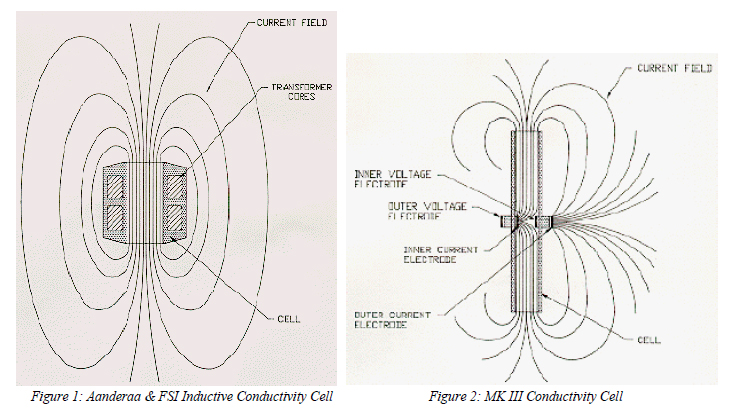
With inductive conductivity sensors (Figure 1), the electrical current flows in closed paths through the hole in the transformer cores. The magnitude of this current (and therefore the output signal from the sensor) depends on the field density along the path. In the area away from the hole, the paths are widely separated and the resistance is low. In the hole through the cell, the paths converge and the resistance is higher; the area immediately exterior to the hole will also contribute significantly to the total resistance. But typically about 20% of the resistance occurs outside the relatively well-defined hole itself.2
In a manner analogous to the hole in an inductive sensor, an electrode cell's length and crosssectional area serve to define the measured volume of seawater; however, in most electrode cells, some of the cell's sensitivity is similarly external. For example, in the 3 cm rectangular electrode cell used on the Neil Brown MK III CTD (Figure 2), the electrical current completes its path outside the cell. As a result, about 11% of the measurement is external.3
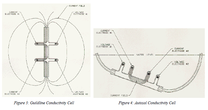
A second type of electrode cell is used in the Guildline CTD (Figure 3). Here, about 2/3 of the electrical current never leaves the inner cell volume. Operated as an in-situ conductivity cell, the voltage difference between V1 and V2 causes an additional electrical current to flow externally.
The Guildline Autosal uses an adaptation of the Guildline CTD cell (Figure 4) in which tubes connected to the cell come out into the air. This prevents the flow of electrical current external to the cell. The Autosal's notable accuracy then results from the fact that the cell's hard parts uniquely define the cell constant.
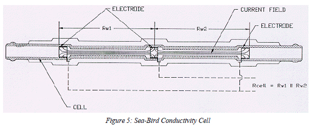
Unlike all inductive and other electrode cells, the Sea-Bird cell (Figure 5) has zero external field because its outer electrodes are connected together; no voltage difference exists to create an external electrical current4. This is a two-terminal cell in which the electrode resistances are in series with (and indistinguishable from) the cell resistance proper. Because the electrode resistances are low and the cell resistance high, errors resulting from changes in the electrode resistances are small. On the other hand, the sample volume -- entirely determined by the cell's hard parts -- is immune to proximity errors and readily protected from fouling by anti-biology (toxic) gatekeepers placed at the ends of the cell.
Advantages and disadvantages of available sensor types
1. Inductive Sensors
The main advantages of inductive sensors are robust construction, and that to preserve the geometry factor they can be cleaned with soap or solvents and a brush. There are no electrodes, so there is no possibility of their damage. Inductive sensors usually have a fairly large hole, which permits free flushing.
The main disadvantages are that a significant part of the measurement is external (e.g., FSI's brochures make the statement "no metallic part intrusion within 3 inch spherical radius" of the inductive sensor). Major consequences result from this external field:
A. The external volume (3" radius) is very difficult (impossible?) to protect from the effect of biological fouling or intrusion of adjacent objects such as cables and other sensor housings. While FSI's warning specifies metallic intrusion, the intruding object need only be of different conductivity than the seawater for proximity errors to occur.
Note that antifoul painting of the sensor surface is just as likely to cause errors as to prevent them. This is because any practical paint thickness will alter the cell geometry. Even a paper-thin 100 micron coating of paint will change the indicated salinity by more than 0.7 psu, an offset that will change as the antifoul toxin leaches out of the paint.
Antifoul material other than paint -- if placed close to the sensor -- will cause proximity errors. If placed sufficiently distant, its antifoul effectiveness will be poor.
B. Mounting of the sensor to companion packages (ALACE floats, current meters, AUVs, etc.) must be undertaken to avoid intrusion into the external area. Because final package geometry influences the results, the calibration must be performed on the fully assembled package.
C. The mounting strut used to reduce proximity effects has proven to be fragile
D. Calibration is awkward because clearance in the calibration baths must be provided for the external field. Calibration is especially inconvenient if the sensor is already mounted to a relatively large companion package such as an ALACE float (see item B above).
A secondary disadvantage of the inductive cells is the requirement for oil-filling and pressurebalance ports. These are a source of unreliability and tend to drive up initial and long term costs. Potted cells that forego pressure balance are susceptible to plastic deformation and creep, leading to geometry changes and drift, especially in profiling applications.
2. Sea-Bird Sensors
The main advantages of Sea-Bird's electrode cells derive from their fully internal field. Because the field is internal, small amounts of antifoul material placed at the ends of the cell (but not in it) are demonstrably effective in preventing internal fouling and attendant drift.
Since there is no external field:
A. There is no proximity effect. The SBE cell does not require mounting on the end of a fragile strut, and mechanical protection is easily arranged. Its rugged reliability has been proven in more than 6000 SBE cells that have been deployed long term and unattended -- large numbers on multiple deployments spanning many years.
B. SBE conductivity sensors can be calibrated in small baths without concern for proximity effects. We routinely calibrate 10 sensors in one automatically controlled bath of less than 50 liters capacity, obtaining out of the box accuracy corresponding to better than 0.005 psu.
The primary disadvantage of the SBE sensor is its relatively poor flushing. While this is actually advantageous in that it enhances the antifoul capabilities of the cell, it is a drawback where very small spatial scales must be resolved. Generally, the SBE cell will give good results for measurements on second time scales for flow rates of 10 cm/second or more. Moored applications (with measurements typically on minute boundaries or greater) have exhibited scientifically satisfactory data even in lowflow environments.
A secondary disadvantage is that the SBE cell cannot be cleaned in the field. This is not generally important in autonomous or moored applications where no one will be there to do the cleaning!
Common misconceptions about Sea-Bird conductivity cells
"The electrodes will corrode." The Sea-Bird cell's platinum electrodes are completely inert in seawater. They are AC coupled to preclude any galvanic effects. After thousands of deployments there is zero evidence of electrode corrosion or other electrode degradation in Sea-Bird cells.
"Two-terminal cells cannot give high accuracy." Published results prove otherwise. The Sea-Bird cell's large electrode area combined with the cell's high resistance override the limitations of twoterminal technique; for a negligible price in theoretical accuracy, the two-terminal configuration yields the enormous benefits of zero external field. Field deployments show the Sea-Bird cell to be at least as accurate, even for profiling, as the 4-terminal NBIS MKIII cell. Since Sea-Bird cells are protected from bio-fouling and are insensitive to proximity effects, they have proven much more accurate in moored and autonomous applications.
"Sea-Bird's cell is fragile." The robustness of the borosilicate glass from which it is made is not much different from the ceramic used in competing designs. Because there is no external field, the Sea-Bird cell doesn't need strut mounting and it is practical to protect the cell with a mechanical guard. Thousands of successful deployments have been made with Sea-Bird cell-equipped instruments
"You can't clean the Sea-Bird cell with a KimWipe or a bottle brush." True, but there will not be anyone riding an ALACE float or an ocean mooring to clean an inductive cell, either.
"Electrodes foul. Inductive cells don't have electrodes to foul." The issue is not just whether electrodes foul, but whether the cell fouls. The fundamental unprotectability of inductive sensors results in fouling of the whole cell. This changes the cell constant and leads to unacceptable drift.
"Sea-Bird conductivity sensors are expensive." We make only high-accuracy sensors and they are generally less expensive than competitive high accuracy types. High-accuracy Sea-Bird sensors are more expensive than the "Industrial-OEM" sensors made by FSI.
Summary
Stable measurement of conductivity in unattended biologically active deployments is a proven reality with Sea-Bird sensors. Sea-Bird cells do resist fouling because their lack of external sensitivity permits the use of effective antifoul protection. They are rugged and reliable, as proven by thousands of successful deployments and a wealth of published results.
1Evidence for the primacy of geometric error sources lies in the enormous accumulation of Autosal bottle data suggesting comparable drift rates in SBE and MK III conductivity sensors. That these sensor types, using profoundly different electronics methodologies but having very similar cross sections (13 mm2 for SBE, 16 mm2 for the MK III), drift equally and in the same direction (fresh) over time is readily explained only if geometry errors predominate. The stability of the Guildline Autosal itself offers additional evidence for the benefits deriving from the well-controlled geometry of an internal-field cell.
2A good estimate of the cell constant for an inductive sensor can be made by comparing the resistance imputed from the hole cross-sectional area and length with the readings obtained with a resistor looped through the cell. A typical inductive cell (FSI) has a diameter of about 0.023 m and a length of about 0.045 m, implying a cell constant of about 0.009 m and a resistance at C(35,15,0) of about 25 ohms. Because of the substantial seawater resistance in the current paths outside the cell (about 22% of the total), the actual resistance seen by the electronics is about 32 ohms.
Aanderaa current meters employ a typical inductive cell with a diameter of about 0.0127 m and a length of about 0.029 m. This implies a cell constant of about 0.0103 m and a resistance at C(35,15,0) of about 53 ohms. Because of the substantial seawater resistance in the current paths outside the cell, the actual resistance seen by the electronics is about 65 ohms, indicating that about 18% of the sensitivity occurs outside the hole.
3Gregg, M. C., et al, J. of Phys. Oceanogr., Vol. 12, No. 7, July 1982; pp. 720 - 742. Gregg demonstrates that the MK III 3 cm cell has about 11% of its sensitivity outside the cell.
4The cell resistance for each half of the Sea-Bird cell can be computed from length (0.05 m) and area (1.26E-5 m). Because the two cell halves are electrically in parallel, the net calculable resistance at C(35,15,0) is about 465 ohms. For this resistance, the SBE 4 conductivity sensor's computed output frequency of 9913 Hz compares very closely with the frequency measured at calibration. Calibrated separately and without cell attachments, SBE conductivity sensors are subsequently connected to a pump and TC duct when installed on the SBE 911plus CTD. The repeatedly demonstrated out-of-thebox ability of the SBE 911plus to produce absolute salinities accurate to within a few ppm is evidence for the cell's complete lack of external sensitivity.