.svg)

Support & Resources
Welcome to the Support and Resource hub for expert guidance, technical documentation, and troubleshooting tools. Access FAQs, Technology Guides, technical papers, case studies, app notes, and more, to ensure you are making the best use of your instrumentation.
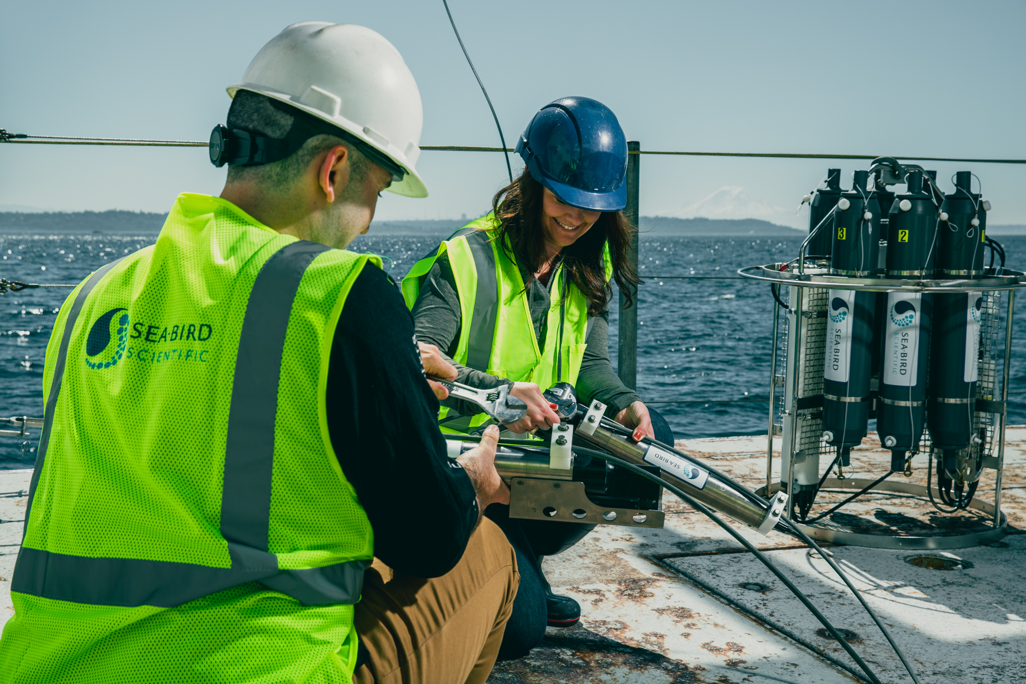
Sea-Bird Scientific provides numerous resources and services to assist in maintaining, troubleshooting, and using your instruments.
FAQs
Have questions? Visit our FAQ page for quick answers, troubleshooting tips, and expert guidance on Sea-Bird Scientific tools.
View our FAQs
Training
Explore Sea-Bird Scientific training offerings for hands-on learning, virtual deep dives, and best practices in ocean and freshwater science
View our training offerings