- PRODUCTS
- MODEL LIST
- APPLICATIONS
- SUPPORT
- SALES/SERVICE
- BLOG
- ABOUT
Login
Guide to Inductive Moorings

Real-time ocean observing systems provide critical information for the study of ecosystems, water quality, and fisheries, as well as data for long-term climate change studies. Wireless (satellite/mobile) telemetry has made real-time, unattended, remote oceanography increasingly practical.
Traditional real-time moorings required failure-prone breakouts for direct cable connections to instruments. These systems also lack flexibility, because the location and type of each instrument is fixed once the cable is manufactured.
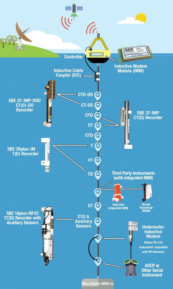
Sea-Bird’s Inductive Modem (IM) system provides reliable, real-time data transmission for up to 100 instruments that can be positioned or repositioned at any depth. The IM system supports both autonomously operating instruments and those that require a command to take a measurement and return the data. Global commands to take and store a measurement can be sent to all instruments on the mooring line. Data is retrieved by sending a command to each instrument, using its unique ID, to transmit its data.
Sea-Bird’s IM system transmits commands and data between an Inductive Modem Module (IMM) in the surface buoy and up to 100 IM-enabled instruments on a plastic-jacketed steel mooring line, without the need for breakouts
-
- Underwater Instruments – up to 100 IM-enabled instruments can be on the mooring cable, including:
Instrument Temperature? Conductivity? Pressure (optional)? Other? / Notes SBE 16plus-IM V2 x x x Up to 7 auxiliary sensors, such as dissolved oxygen, turbidity, fluorescence, PAR, etc. SBE 37-IM x x x SBE 37-IMP x x x SBE 37-IMP-ODO x x x Dissolved oxygen SBE 39plus-IM x x UIMM Adapts RS-232 instruments (acoustic current meters, Doppler profilers, optical sensors, etc.) for IM moorings - Inductive Modem Module (IMM) – small printed circuit board housed in buoy that communicates with IM instruments and interfaces to a computer/data logger via RS-232 serial connection. Commands to IM instruments can be global (for example, command all instruments to take and store a measurement now) or addressed to an individual instrument (for example, send your data now). Data can be received from only one instrument at a time.
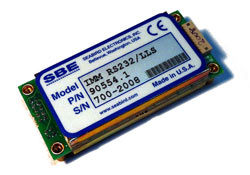
Inductive Modem Module (IMM) - Inductive Cable Coupler (ICC) – couples mooring line to IMM via a waterproof bulkhead connector through the buoy hull. Clamps along the plastic-jacketed portion of mooring cable, below the seawater ground. For typical moorings; optional.
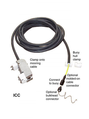
Inductive Cable Coupler (ICC) - Mooring cable* – plastic-jacketed steel mooring line, used as both the data transmission line and the mooring support line for the instruments. This type of rope is frequently also used for non-inductive oceanographic moorings because of the corrosion resistance provided by the plastic jacket. It is not necessary to provide any electrical connection between instrument and cable; expensive and unreliable electro-mechanical cables and terminations are not needed to get real-time data.
- Buoy controller* – housed in buoy and connected to IMM via RS-232. Programmed to send commands to IMM to poll each underwater IM instrument for data and send data to shore via mobile or satellite transmission.
- Surface buoy* - houses IMM, controller/data logger, telemetry transmitter/receiver, and power supply.
- Shore installation* – houses telemetry receiver (and optional transmitter, permitting shore control of buoy function) and computer for logging, processing, and displaying data.
- Underwater Instruments – up to 100 IM-enabled instruments can be on the mooring cable, including:
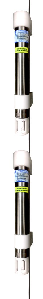
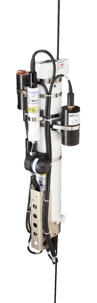
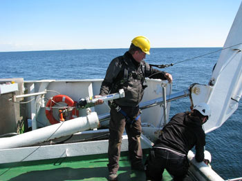
Above: SBE 39plus-IM Temperature (optional pressure) Recorders with titanium housings on a mooring line
The IM system can accommodate a wide variety of instruments for nearly any type of measurement. Sea-Bird Scientific manufactures IM versions of a number of instruments, measuring various combinations of temperature, conductivity, pressure, dissolved oxygen, and data from integrated auxiliary sensors.
Also available is an Underwater Inductive Modem Module (UIMM) that allows instruments from other manufacturers to be integrated with an IM system. The UIMM consists of an IMM in a small pressure housing, with a built-in inductive cable coupler and cable clamp. The UIMM is user-configured via RS-232 to send and receive commands to control the serial instrument and receive or retrieve data. An RS-232 serial output instrument simply plugs into the UIMM end cap for deployment.
An IMM and a cable coupler can also be integrated at the development stage in RS-232 serial output instruments from other manufacturers.
An inductive modem uses electrical current loops to transmit information; current flowing in a wire loop induces current to flow in a loop that passes through it. In Sea-Bird's IM system:
- The first loop is formed by the coupler connection of the surface buoy to the mooring cable.
- The second loop is formed by the mooring cable and the seawater; the cable is bare metal on the top and bottom and insulated in the middle.
- The third loop is at each underwater instrument.
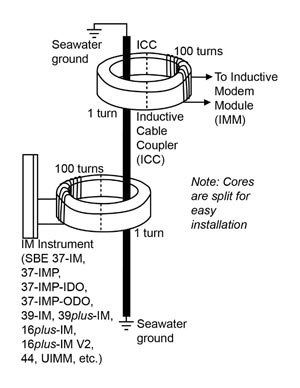
Each cable coupler contains a transformer. The toroidal transformer consists of a circular ferrite core and two coils that share a magnetic field. Each coupler is made up of two halves, allowing it to clamp around the cable, so the cable does not need to be threaded through the unit.
For typical saltwater applications, the maximum transmission length is approximately 6,000 meters. In fresh water, with its lower conductivity, good communications can be obtained over 1,000 meters.
The first Sea-Bird IM systems, utilizing SBE 37-IM MicroCAT CT and CTD instruments, were deployed in the western Pacific in 1998 by JAMSTEC (Japan Agency for Marine – Earth Science and Technology) for the Triton array.
The Triton array is still in operation today and continues to use IM telemetry to deliver real-time data from sensors placed at depths up to 750 meters on a 4,000-meter mooring. The present buoy configuration includes 11 Sea-Bird MicroCAT CT and CTD instruments programmed to take a measurement every 10 minutes and report an hourly mean to the buoy controller via the IM system.
More than 3,000 Sea-Bird IM instruments have been deployed worldwide in the ensuing 18 years.
1
WQM with BPA50-IM Inductive Modem Battery Pack2
SBE Inductive Cable Coupler connects to Inductive Modem Module in buoy3
SBE Underwater Inductive Modem Module integrates RS -232 instrument to IM mooring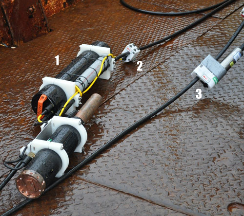
Sea-Bird’s IM system was used in dredge monitoring for the Fehmarnbelt Fixed Link project (an immersed tunnel that is being constructed to connect the Danish island of Lolland with the German island of Fehmarn).
Anders Jensen, business area manager for survey and monitoring for the project’s environmental consultant DHI, had this to say about their experience:
“We built our buoy systems for the Fehmarnbelt Fixed Link project with (Sea-Bird Scientific) WQMs and Sea-Bird Inductive Modem technology, with great success. . . As a full-service provider of marine environmental-monitoring systems, DHI expects and our clients demand reliability. We build our buoys to provide this with near real-time delivery of data to the web and data redundancy in the instruments on the buoy as back up. DHI’s Aquaguard controller communicates with the instruments using Sea-Bird’s Inductive Modem technology, which has been the key to providing robust communication capability. Data transmission from the monitoring site assures our clients that their monitoring program is meeting their specifications and saves time and effort for everyone by reducing servicing trips.”
The Finnish Meteorological Institute (FMI) deployed an IM system in the Baltic Sea near Utö Island. Tero Purokoski of FMI stated, “Oceanographic measurements at Utö have been conducted since 1900. Traditionally, the data has been used for monitoring climate change and variability in the Baltic Sea, but now the Station is also part of the European Integrated Carbon Observation System (ICOS). One of the science questions examines the role of the ocean physical processes on atmosphere-ocean gas exchanges. The data is also assimilated into operational oceanography models, improving our forecasting skill for the Baltic Sea.”
FMI’s system consists of a surface buoy with an SST (sea surface temperature sensor), GPS, controller, and Iridium satellite connection. Underwater are SBE 37-IMP CT (4), SBE 37-IMP CTD (1), and SBE 37-IMP-ODO CTD with integrated optical dissolved oxygen (2) instruments. The CT and CTD instruments take a measurement every five minutes, the CTD-DO instruments take a measurement every thirty minutes, and the controller queries for data from the last measurement every thirty minutes. The surface buoy has enough battery power to operate for twelve months of uninterrupted data collection.
- Application Note 92: Real-Time Oceanography with Inductive Moorings and the Inductive Modem Module (IMM)
- Sea-Bird Inductive Modem Instruments. www.seabird.com/products/inductive-modem-instruments
- JAMSTEC (Japan Agency for Marine – Earth Science and Technology) Triton Array. www.jamstec.go.jp/jamstec/TRITON/real_time/
- Utö Atmospheric and Marine Research Station. en.ilmatieteenlaitos.fi/uto
- Environmental background studies for the Fehmarnbelt Fixed Link. www.dhigroup.com/global/news/imported/2012/1/30/environmentalbackgroundstudiesforthefehmarnbeltfixedlink