.svg)

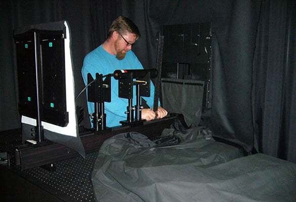
 Positive pressure and sticky mats shun light-scattering dust from a room in Philomath, Oregon—the site of a new brand new radiometer calibration facility. As Sea-Bird Scientific’s facility in Halifax, Nova Scotia (formerly Satlantic) shuttered its doors, radiometer production and calibration moved across the continent, setting up shop in Sea-Bird Scientific’s Philomath site (formerly WET Labs). As with any new calibration lab, rigorous testing is crucial to determine if the new Oregon facility can meet Halifax quality. In early 2017, Sea-Bird Scientific moved production and calibration of all radiometers from Halifax, Nova Scotia (formerly Satlantic) to Philomath, Oregon (formerly WET Labs). Already an expert in calibrating optical sensors, the former WET Labs facility was a natural choice to adopt radiometer calibration. With a one-year overlap, the two facilities leveraged shared knowledge to replicate and improve calibration procedures during the transfer, applying the rigorous scientific principles at the heart of the radiometer product line to the new calibration lab. Already an established and trusted facility, Halifax acted as the baseline for calibration quality, having previously been vetted by lab intercomparisons in the past. As with every well-controlled experiment, the calibration quality from the former Satlantic labs continuously vetted the development of the new facility, testing sensors calibrated in Philomath to shed light on sources of error. Meanwhile, on the other end of North America, the Philomath lab represented a new beginning for radiometer calibration—a chance to replicate and expand on existing procedures—and the opportunity to overcome old and new challenges. Both labs are similar in design—they utilize similar, almost identical equipment and geometry, and produce comparable calibration quality and repeatability. The process of revisiting the familiar calibration procedure in a new environment offered new analysis opportunities; metadata such as lamp voltage and room temperature recorded alongside sensor output granted fresh insight into error sources in calibration quality, and the opportunity to fix issues as they arise. The result: A growing, improving successor to the calibration labs in Halifax.
Read the Full White Paper
Positive pressure and sticky mats shun light-scattering dust from a room in Philomath, Oregon—the site of a new brand new radiometer calibration facility. As Sea-Bird Scientific’s facility in Halifax, Nova Scotia (formerly Satlantic) shuttered its doors, radiometer production and calibration moved across the continent, setting up shop in Sea-Bird Scientific’s Philomath site (formerly WET Labs). As with any new calibration lab, rigorous testing is crucial to determine if the new Oregon facility can meet Halifax quality. In early 2017, Sea-Bird Scientific moved production and calibration of all radiometers from Halifax, Nova Scotia (formerly Satlantic) to Philomath, Oregon (formerly WET Labs). Already an expert in calibrating optical sensors, the former WET Labs facility was a natural choice to adopt radiometer calibration. With a one-year overlap, the two facilities leveraged shared knowledge to replicate and improve calibration procedures during the transfer, applying the rigorous scientific principles at the heart of the radiometer product line to the new calibration lab. Already an established and trusted facility, Halifax acted as the baseline for calibration quality, having previously been vetted by lab intercomparisons in the past. As with every well-controlled experiment, the calibration quality from the former Satlantic labs continuously vetted the development of the new facility, testing sensors calibrated in Philomath to shed light on sources of error. Meanwhile, on the other end of North America, the Philomath lab represented a new beginning for radiometer calibration—a chance to replicate and expand on existing procedures—and the opportunity to overcome old and new challenges. Both labs are similar in design—they utilize similar, almost identical equipment and geometry, and produce comparable calibration quality and repeatability. The process of revisiting the familiar calibration procedure in a new environment offered new analysis opportunities; metadata such as lamp voltage and room temperature recorded alongside sensor output granted fresh insight into error sources in calibration quality, and the opportunity to fix issues as they arise. The result: A growing, improving successor to the calibration labs in Halifax.
Read the Full White Paper
Related Posts
White Papers
White Papers